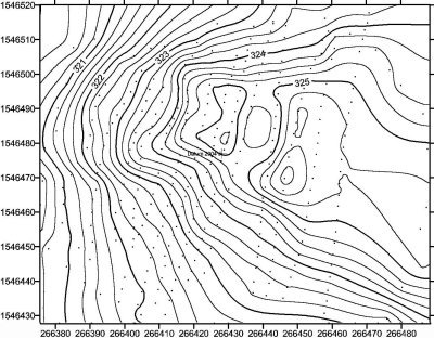
Earlier we saw how to create contours based on a points’ network taken in the field. Now we’ll see how to do it, from existing curves in a scanned map.
As we did with the design of roads, let’s split the process into steps, so that the post won’t go longer than a snake fart.
Inserting the image
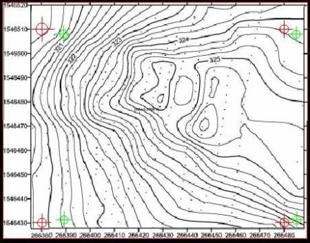
For this, if we have marginal coordinates in UTM, the work is greatly simplified. In this case, we identify the coordinate intersections near the extremes; if we have the corner’s intersections would be the best.
266380,1546430
266480,1546430
266380,1546510
266480,1546510
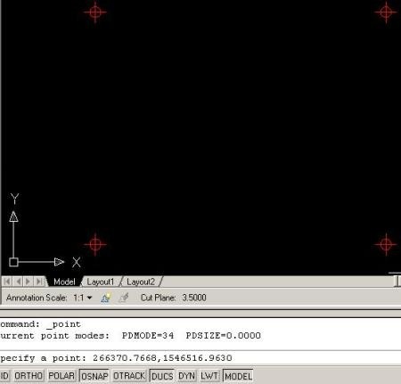
Points are inserted with the command point, and entering the coordinate separated by a comma, as shown in the picture below. To change the format point to a visible symbol, it’s done from Format> point style. But because these Civil 3D versions complicates the process of finding the Tools menu, you can write like in the old way: ddptype from the command line, then press enter and choose the type of point.
In this part, I miss MicroStation, where a point is a line of zero-length, and can have dynamic thickness with the map view.
Now we insert the image using Insert> Raster image reference. We left enabled the possibilities to put Insertion point and scale from the screen.
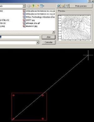 Then you place a point at coordinates’ left and move the mouse until you can see that the image has the approximate size.
If the image covers the points, it must be sent back. This is done with Tools> Display order> Send to back.
Georeferencing the image.
We’ll need points on the picture that must be equivalent to those we have entered through coordinates. For that, we join the marginal lines, in order to find the intersections.
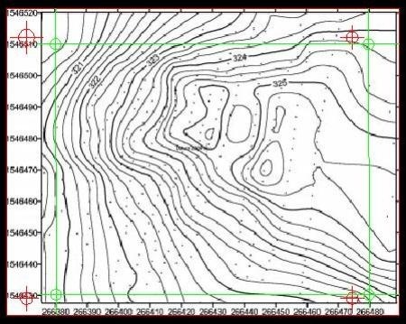
Using Map> Tools> Rubber Sheet command, as we use it a few days ago to transform vectors, we indicate the green dot as a base, then the red one as reference. When we have already done everything with the four dots, then we do enter and the command asks us to select the objects to transform. We write the letter S for the Select option, and touch the image, then we do enter the last time and there we have it.
Quite similar to what it does the Warp of Microstation’s Raster Manager. As we explained before, when we want to georeference images, it’s better from Google Earth.
And now look how the image matches the red dots, so the greens can be deleted. Now the image is georeferenced and with an appropriate scale to start scanning.
To complete the exercise and make the contours see the next step.
 Autocad Software, Bentley Microstation, Gis Google Earth, Gis System Geomate Provides Services For Complete Gis Software And Solutions, Autocad Software, Autocad Courses, Bentley Microstation, Microstation Software, Gis Google Earth, Open Source Gis And More.