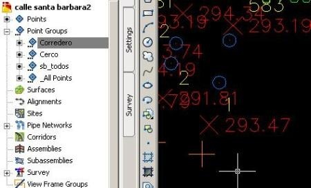
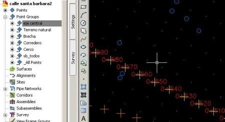
In the previous post we saw how to import points, now we’ll see how to filter them to get a better sense of what we have. The points that we have, have the following attributes:
FENCE, SLIDING, GAP
Then the rest is nothing, so we assume that it is a natural terrain and there is also the central axis points are shown with stations 0 +000 0 +10, 0 +20 … until it reaches 0 +650
Customizing the fence points
What we want is to visualize the type of points based on their table attributes, so in the point group we do right-click and select “New”.

Then we call it “Fence” and edit the point’s properties (point style) creating a new style by setting the following:
- In “Information” will call “Fence” (Cerco)
- In “Marker” we’ll choose an X
- In “Display” we will change it to orange color
- Then, do “OK”
We do the same with the label (point label style), but in this case we want the text won’t be visible so for this:
- In “Information” we called it “Fence label”
- In “Layout” we choose “point number”, “Point Description” and “Point elevation” false. There it could be changed the color.
- We Accept


Now to make this style be applied to the points of the fence, select tab “include” make sure the text contains the word “CERCO” (fence), then choose “apply” and check on the “Point list” tab that all points contain that description.
Then we do accept and shall see that the entire fence’s checkpoints have been color with an orange X letter as we have defined.

The sliding points
We will do the same with the attribute “SLIDING”, in this case I will give them a blue wheel, and I will hide the names, elevations and number.
To display the change, regenerate with “re” and “enter.”

The Gap points
If the previous step got’s you an effort, now we must try to regain time, it is the same initial procedure, creating a personal style for each type of points.
In the case of the Gap, I will use green color, as symbol a square and without descriptions. Blocks could be used for this, but it is not my discussion topic for today.
The natural terrain points.
For this, we will make a special selection in this case not in “include” but “exclude” putting the following:
SLIDING, GAP, FENCE, 0 + *
What it means is that all points that don’t contain any description like that will go out, notice that the latter is explained in the next step.
At this point the job should look like this:

The central axis points
In this case, what we do is an “include” placing 0 + *
Which implies that all stations having zero, the plus sign and any other character will be selected. And for doing this we will give it a symbol of +, leaving visible only the station and elevation.

I understand that you customize the latte will cost must to you, but it’s how to test, changing properties to know what it is modified. Finally it should look like:


You can ignore this, but I aware that it will cost you later. Here (*) you can download the file that shows the progress. As you see, it can be distinguished between different kinds of total station’s capture.
NOTE:
(*) This is explained in other post.
 Autocad Software, Bentley Microstation, Gis Google Earth, Gis System Geomate Provides Services For Complete Gis Software And Solutions, Autocad Software, Autocad Courses, Bentley Microstation, Microstation Software, Gis Google Earth, Open Source Gis And More.